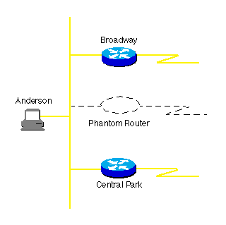

HSRP routers on a LAN communicate among themselves to designate two routers as active and standby. The active router sends periodic hello messages. The other HSRP routers listen for the hello messages. If the active router fails and the other HSRP routers stop receiving hello messages, the standby router takes over and becomes the active router. Because the new active router assumes both the IP and MAC addresses of the phantom, end nodes see no change at all. They continue to send packets to the phantom's MAC address, and the new active router delivers those packets.
HSRP also works for proxy ARP. When an active HSRP router receives an ARP request for a node that is not on the local LAN, the router replies with the phantom's MAC address instead of its own. If the router that originally sent the ARP reply later loses its connection, the new active router can still deliver the traffic.

If complete server redundancy is not feasible due to cost considerations, mirroring or duplexing of the file server hard drives is a good idea. (Duplexing is the same as mirroring with the additional feature that the two mirrored hard drives are controlled by different disk controllers.)
Most IP routing protocols can load balance across six parallel links that have equal cost. To support load balancing, keep bandwidth consistent within a layer of the hierarchical model so that all paths have the same cost. (Cisco's IGRP and Enhanced IGRP are exceptions because they can load balance traffic across multiple routes that have different metrics, using a feature called "variance.")
A hop-based routing protocol does load balancing over unequal bandwidth paths as long as the hop count is equal. Once the slower link becomes saturated, the higher-capacity link cannot be filled which is called pinhole congestion. Pinhole congestion can be avoided by designing equal bandwidth links within one layer of the hierarchy or by using a routing protocol that takes bandwidth into account.
IP load balancing depends on which switching mode is used on a router. Process switching load balances packet by packet. Fast, autonomous, silicon, optimum, distributed, and NetFlow switching load balance destination by destination, because the processor caches the encapsulation to a specific destination for these types of switching modes. Switching modes are discussed in more detail in Section 3 of Module 2, "Provision Hardware and Media for the WAN."
We already talked about keeping bandwidth consistent within a given layer of a hierarchy to facilitate load balancing. Another reason to keep bandwidth consistent within a layer of a hierarchy is that routing protocols converge much faster if multiple equal-cost paths to a destination network exist.
By using redundant, meshed network designs, you can minimize the effect of link failures. Depending on the convergence time of the routing protocols being used, a single link failure will not have a catastrophic effect. We will talk more about routing convergence in Section 5 of Module 2, "Select Routing and Bridging Protocols."
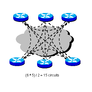
A network can be designed as a full mesh or a partial mesh. A full-mesh network provides complete redundancy. It also provides good performance because there is just a single-hop delay between any two sites.
The number of links in a full mesh is n(n-1)/2, where n is the number of routers. Each router is connected to every other router. Divide the result by 2 to avoid counting Router X-Router Y and Router Y-Router X as two different links.

A full mesh can be expensive to implement due to the required number of links. In addition, there are practical limits to scaling for groups of routers that broadcast routing updates or service advertisements. As the number of router peers increases, the amount of bandwidth and CPU resources devoted to processing broadcasts increases.
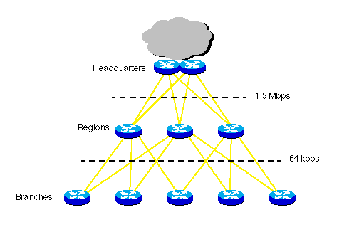
Keep broadcast traffic at less than 20 percent of the bandwidth of each link to limit the number of peer routers that can exchange routing tables or service advertisements. When planning redundancy, follow guidelines for simple, hierarchical design. A classic hierarchical and redundant enterprise design is shown in the following graphic. It uses a partial-mesh rather than full-mesh architecture.

In switched networks, switches can have redundant links to each other. Because Cisco switches implement the IEEE 802.1d spanning-tree algorithm, loops can be avoided. The spanning-tree algorithm guarantees that there is one and only one active path between two network stations. The algorithm permits redundant paths that are automatically activated when the active path experiences problems.
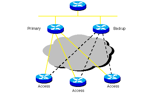
Because WAN links are often critical pieces of the internetwork, redundant media is often deployed in WAN environments. Backup links can be provisioned so that they become active when a primary link goes down or becomes congested.

Often backup links use a different technology. For example, a leased line can be in parallel with a backup dial-up line or ISDN circuit. By using what is called "floating static routes," you can specify that the backup route has a higher administrative distance, so it is not normally used unless the primary route goes down.
When provisioning backup links, learn as much as possible about the actual physical circuit routing. Different carriers sometimes use the same facilities, meaning that your backup path is susceptible to the same failures as your primary path. You should do some investigative work to ensure that your backup really is a backup.
Backup can be combined with load balancing and channel aggregation. Channel aggregation means that a router can bring up multiple ISDN B channels as bandwidth requirements increase.
Cisco supports the Multilink Point-to-Point Protocol (MPPP), which is
an Internet Engineering Task Force (IETF) standard for ISDN B-channel aggregation.
MPPP does not specify how a router should accomplish the decision-making
process to bring up extra B channels. Instead, it seeks to ensure that
packets arrive in sequence at the receiving router. Then the data is encapsulated
within PPP and the datagram is given a sequence number. At the receiving
router, PPP uses this sequence number to recreate the original data stream.
Multiple channels appear as one logical link to upper-layer protocols.
Click on the Back button in your browser or click here to go back to Section 1 of Module 2, "Design the Topology."