Table of Contents

Module 2 - Design the Network Structure
Section 2 - Provision Hardware and Media for the LAN
Section Objectives
Upon completion of this section, you will be able to:
-
Recognize scalability constraints and issues for standard LAN technologies.
-
Recommend Cisco products and LAN technologies that will meet a customer's
requirements for performance, capacity, and scalability in small- to medium-sized
networks.
-
Update the network topology drawing you created in the previous section
to include hardware and media.
Time Required to Complete This Section
Approximately 2 hours
Completing This Section
Follow these steps to complete this section:
1. Study the reading assignment.
2. Click on any links that you see in the reading assignment and review
the information that appears.
3. Review any tables and job aids that appear in the reading assignment.
4. Review the case studies at the end of this section.
5. Complete the questions in each case study.
6. Review the answers provided by our internetworking experts.
Resources Required to Complete This Section
To complete this section, you will need:
-
Access to the World Wide Web and Cisco's Web site
-
A downloaded, printed copy of this section
-
Paper and pencil
-
Topology drawings you created in Section 1 of Module 2
-
Access to the Cisco Reseller Product Selection Tool
-
Open the/tools directory on the "Designing Cisco Networks" CD
-
Double-click Cisco Reseller Product Selection Tool (Crpst.exe) to start
the tool
-
"Small and Medium Business Solution Guide" included with this course
Reading Assignment
Switching versus Routing in Network Design
When provisioning internetworking devices for small- to medium-sized networks,
you need to decide when LAN switches are appropriate and when routers are
appropriate.
In general, incorporating switches in small- to medium-sized network
designs will provide you the following advantages:
-
High bandwidth
-
Low cost
-
Easy configuration
If you need internetworking services, routers are needed. Routers offer
the following services:
-
Broadcast firewalling
-
Hierarchical addressing
-
Communication between dissimilar LANs
-
Fast convergence
-
Policy routing
-
QoS routing
-
Security
-
Redundancy and load balancing
-
Traffic flow management
-
Multimedia group membership
Switching Services
Some services are becoming available on switches also. For example, support
for multimedia often requires a protocol such as the Internet Group Management
Protocol (IGMP) that allows workstations to join a group that receives
multimedia multicast packets. Cisco now allows Catalyst switches to participate
in this process by using the Cisco Group Management Protocol (CGMP). One
router will still be needed, but you will not need a router in every department
of a company because with CGMP switches can communicate with the router
to determine if any users attached to them are part of a multicast group.
Switching and bridging sometimes result in non optimal routing of packets
because every packet must go through the root bridge of the spanning tree.
When routers are used, the routing of packets can be controlled and designed
for optimal paths. Cisco supports improved routing and redundancy in switched
environments by allowing one instance of the spanning tree per VLAN.
Problems Solved with Internetworking Devices
The decision to use an internetworking device depends on which problems
you are trying to solve for your client. As we discussed in the introduction
to this course, customer problems can be categorized as follows:
Media Problems
Media problems refer to an excessive number of collisions on Ethernet and
long waits for the token in Token Ring or FDDI. Media problems are caused
by too many devices, all with a high offered load for the network segment.
Media problems can be solved by dividing a network into separate segments
using one or more switches.
Protocol Problems
Protocol problems are caused by protocols that do not scale well, for example,
protocols that send an excessive number of broadcasts. Protocol problems
can be solved by dividing a network into separate segments using one or
more routers.
Need to Transport Large Payloads
This category includes the need to offer voice and video network services.
These services may require much more bandwidth than is available on a customer's
network or backbone. Transport problems can be solved by using high-bandwidth
technologies, such as Fast Ethernet or ATM.
Bandwidth Domains
When using switches or bridges, everything associated with one port is
a bandwidth domain. In the case of an Ethernet switch, a bandwidth domain
is also known as a collision domain.
A broadcast domain includes associated with one port on a router. All
broadcasts from any host in the same broadcast domain are visible to all
other hosts in the same broadcast domain. Desktop protocols such as AppleTalk,
NetBIOS, IPX, and IP require broadcasts or multicasts for resource discovery
and advertisement. Hubs, switches, and bridges forward broadcasts and multicasts.
Routers do not forward broadcasts.
All workstations within one bandwidth domain compete for the same LAN
bandwidth resource. All traffic from any host in the bandwidth domain is
visible to all the other hosts. In the case of an Ethernet collision domain,
two stations can transmit at the same time, causing a collision.
Segmenting the Network Using Switches
When analyzing your customer's current network and future needs, as we
discussed in Module 1, determine if bandwidth domains need to be segmented
using switches. Ethernet networks should be segmented if the network utilization
is above approximately 40 percent for long periods of time. Token Ring
and FDDI networks should be segmented if network utilization is above approximately
70 percent for long periods of time.
Broadcast Radiation
Broadcast radiation refers to the way that broadcasts and multicasts radiate
from the source to all connected LANs in a flat network, causing all hosts
on the LAN to do extra processing. When broadcasts and multicasts are more
than approximately 20 percent of the traffic on a LAN, performance degrades.
Scalability for Flat Networks
There is an upper limit to the size that flat switched/bridged networks
can reach before broadcast radiation overwhelms the CPUs of the hosts.
The limits are shown in the following table. These numbers are provided
as a guide, based on the number of workstations on a LAN or VLAN. Actual
workstation limits depend on factors such as:
-
Broadcast/multicast load
-
IP addressing constraints
-
Inter-VLAN routing requirements
-
Management and fault isolation constraints
-
Traffic flow characteristics
Scalability Constraints for Flat (Switched/Bridged) Networks
|
Protocol
|
Maximum Number of Workstations
|
| IP |
500 |
| IPX |
300 |
| AppleTalk |
200 |
| NetBIOS |
200 |
| Mixed |
200 |
When connecting LANs or VLANs via one or more routers, you need to understand
the characteristics of the network traffic. It is also important to understand
the performance of the router(s) you plan to use in the network design.
We will talk more about router performance and capacity in the next section,
"Provision Hardware and Media for the WAN."
Campus LAN Design
Campus LANs are easiest to design when the traffic obeys the 80/20 rule,
which states that 80 percent of traffic is local to a LAN or VLAN and only
20 percent of the traffic goes to a different LAN or VLAN. This is the
case when users primarily access departmental servers and the LANs or VLANs
are subdivided by department. However, with the emergence of server farms
and corporate Web servers, the 80/20 rule does not always apply. In these
cases, it is important to provision bandwidth and routers carefully to
avoid congestion and poor performance.
Cisco Switches
Cisco's Catalyst family is a comprehensive line of high-performance switches
designed to help users easily migrate from traditional shared LANs to fully
switched networks. The Cisco Catalyst family includes many products, such
as:
-
Catalyst 5000 switching system
-
Catalyst 1900/2820 ethernet switches
Refer to the "Small and Medium Business Solution Guide" that came with
this course for information about the complete Cisco Catalyst family for
small- and medium-sized businesses.
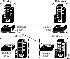
The following diagram shows a sample switched campus network using Catalyst
5000 series switches.
Provisioning Switches, Routers, Access Servers, and Other Cisco Hardware
When provisioning Cisco hardware, use the following documents to gather
information on ports, interfaces, slots, memory, processors, power supplies,
prices, and so on.
-
Cisco Reseller Product Selection Tool, included on this CD or with the
course on Cisco's Web site
-
"Small and Medium Business Solution Guide," included with this course
-
Price list (To obtain a copy of the current Cisco price list, log in to
the Reseller's Web site using your reseller account.)
Provisioning Network Media
Before doing the case study, review the following table that you can use
when provisioning networks:
Scalability Constraints for IEEE 802.3
|
|
10Base5
|
10Base2
|
10BaseT
|
100BaseT
|
| Topology |
Bus |
Bus |
Star |
Star |
| Maximum Segment Length (meters) |
500 |
185 |
100 from hub to station |
100 from hub to station |
| Maximum Number of Attachments per Segment |
100 |
30 |
2 (hub and station or hub-hub) |
2 (hub and station or hub-hub) |
| Maximum Collision Domain |
2500 meters of 5 segments and 4 repeaters; only 3 segments
can be populated |
2500 meters of 5 segments and 4 repeaters; only 3 segments
can be populated |
2500 meters of 5 segments and 4 repeaters; only 3 segments
can be populated |
See the Ethernet Design Rules Section that follows |
The most significant design rule for Ethernet is that the round-trip
propagation delay in one collision domain must not exceed 512 bit times,
which is a requirement for collision detection to work correctly. This
rule means that the maximum round-trip delay for a 10-Mbps Ethernet network
is 51.2 microseconds. The maximum round-trip delay for a 100-Mbps Ethernet
network is only 5.12 microseconds because the bit time on a 100-Mbps Ethernet
network is 0.01 microseconds as opposed to 0.1 microseconds on 10-Mbps
Ethernet.
To make 100-Mbps Ethernet work, there are much more severe distance
limitations than those required for 10-Mbps Ethernet. The general rule
is that a 100-Mbps Ethernet has a maximum diameter of 205 meters when UTP
cabling is used, whereas 10-Mbps Ethernet has a maximum diameter of 2500
meters.
Scalability Constraints for 10-Mbps Fiber Ethernet Networks
The following table provides some guidelines to help you choose the right
media for your network designs.
Scalability Constraints for 10-Mbps Fiber Ethernet
| |
10BaseFP
|
10BaseFB
|
10BaseFL
|
Old FOIRL
|
New FOIRL
|
| Topology |
Passive star |
Backbone or repeater fiber system |
Link |
Link |
Link or star |
| Allows DTE (end-node) Connections? |
Yes |
No |
No |
No |
Yes |
| Maximum Segment Length (meters) |
500 |
2000 |
1000 or 2000 |
1000 |
1000 |
| Allows Cascaded Repeaters? |
No |
Yes |
No |
No |
Yes |
| Maximum Collision Domains in Meters |
2500 |
2500 |
2500 |
2500 |
2500 |
10BaseF is based on the FOIRL specification, which includes 10BaseFP,
10BaseFB, 10BaseFL, and a revised FOIRL standard. The new FOIRL allows
DTE (end-node) connections, rather than just repeaters, as allowed with
the older FOIRL specification.
Details on 100-Mbps Ethernet Topologies
Understanding Collision Domains
The overriding design rule for 100-Mbps Ethernet networks is that the round-trip
collision delay must not exceed 512bit times. However, the bit time on
a 100-Mbps Ethernet network is 0.01 microseconds as opposed to 0.1 microseconds
on a 10-Mbps Ethernet network. Therefore the maximum round-trip delay for
a 100-Mbps Ethernet network is 5.12 microseconds as opposed to the more
lenient 51.2 microseconds in a 10-Mbps Ethernet network.
For a 100-Mbps Ethernet to work, you must impose distance limitations,
based on the type of repeaters used.
100BaseT Repeaters
The IEEE 100BaseT specification defines two types of repeaters:
-
Class I repeaters have a latency of 0.7 microseconds or less. Only one
repeater hop is allowed.
The following table shows the maximum size of collision domains, depending
on the type of repeater:
Maximum Number of Collision Domains for 100BaseT
| |
Copper
|
Mixed Copper and Multimode Fiber
|
Multimode Fiber
|
| DTE-DTE (or Switch-Switch) |
100 meters |
--
|
412 meters (2000 if full duplex) |
| One Class I Repeater |
200 meters |
260 meters |
272 meters |
| One Class II Repeater |
200 meters |
308 meters |
320 meters |
| Two Class II Repeaters |
205 meters |
216 meters |
228 meters |
Example of 100BaseT Topology
Other topologies are possible as long as the round-trip propagation
delay does not exceed 5.12 microseconds (512 bit times.) When the delay
does exceed 5.12 microseconds, the network experiences illegal (late) collisions
and CRC errors.
Checking the Propagation Delay
To determine if other configurations than the standard ones shown will
work, use the following information from the IEEE 802.3u specification.
To check a path to make sure the path delay value (PDV) does not exceed
512 bit times, add up the following delays:
-
All link segment delays
-
All repeater delays
-
DTE delay
-
A safety margin (0 to 5 bit times)
Use the following steps to calculate the PDV:
1. Determine the delay for each link segment
(link segment delay value, or LSDV), including interrepeater
links, using the following
formula. (Multiply by two so that it is a round-trip delay.)
-
LSDV = 2 x segment length x cable delay for this segment.
-
For end-node segments, the segment length is the cable length between the
PHY interface at the repeater and the PHY interface at the DTE. Use your
two farthest DTEs for a worst-case calculation. For interrepeater links,
the segment length is the cable length between the repeater PHY interfaces.
-
Cable delay is the delay specified by the manufacturer if available. When
actual cable lengths or propagation delays are not known, use the delay
in bit times as specified in the following table.
-
Cable delay must be specified in bit times per meter (BT/m).
2. Add together the LSDVs for all segments in
the path.
3. Determine the delay for each repeater in
the path. If model-specific data is not available from the
manufacturer, determine
the class of repeater (I or II).
4. MII cables for 100BaseT should not exceed
0.5 meters each in length. When evaluating system topology,
MII cable lengths
need not be accounted for separately. Delays attributable to the MII are
incorporated
into DTE and repeater
delays.
5. Use the DTE delay value shown in the following
table unless your equipment manufacturer defines a
different value.
6. Decide on an appropriate safety margin
from 0 to 5 bit times. Five bit times is a safe value.
7. Insert the values obtained in the calculations
described in the following formula for calculating the PDV:
-
PDV = link delays + repeater delays + DTE delay + safety margin
8. If the PDV is less than 512, the path
is qualified in terms of worst-case delay.
Round-Trip Delay
The following table shows round-trip delay in bit times for standard cables
and maximum round-trip delay in bit times for DTEs, repeaters, and maximum-length
cables. (The values shown have been multiplied by two to provide a round-trip
delay. If you use these numbers, you need not multiply by two again in
the LSDV formula shown.)
Network Component Delays
|
Component
|
Round-Trip Delay in Bit Times per Meter
|
Maximum Round-Trip Delay in Bit Times
|
| Two TX/FX DTEs |
-- |
100 |
| Two T4 DTEs |
-- |
138 |
| One T4 DTE and one TX/FX DTE |
-- |
127 |
| Category 3 cable segment |
1.14 |
114 (100 meters) |
| Category 4 cable segment |
1.14 |
114 (100 meters) |
| Category 5 cable segment |
1.112 |
111.2 (100 meters) |
| STP cable segment |
1.112 |
111.2 (100 meters) |
| Fiber-optic cable segment |
1.0 |
412 (412 meters) |
| Class I repeater |
-- |
140 |
| Class II repeater with all ports TX or FX |
-- |
92 |
| Class II repeater with any port T4 |
-- |
67 |
Source: IEEE 802.3u - 1995, "Media Access Control (MAC) Parameters,
Physical Layer, Medium Attachment Units, and Repeater for 100 Mb/s Operation,
Type 100BASE-T."
Example Network Cabling Implementation
Refer to the following graphic for this example. Company ABC has all UTP
Category 5 cabling. Two Class II repeaters are separated by 20 meters,
instead of the standard 5 meters. The network administrators are trying
to determine whether this configuration will work.
To ensure that the PDV does not exceed 512 bit times, calculate a worst-case
scenario using DTE 1 and DTE 2, which are 75 meters from their repeaters.
Assume that DTE 1 starts transmitting a minimum-sized frame of 64 bytes
(512 bits). DTE 2 just barely misses hearing DTE 1's transmission and starts
transmitting also. The collision happens on the far-right side of the network
and must traverse back to DTE. These events must occur within 512 bit times.
If they take any longer than 512 bit times, then DTE 1 will have stopped
sending when it learns about the collision and will not know that its frame
was damaged by the collision. To calculate the link delays for the Category
5 cable segments, the repeaters, and DTEs, we will use the values from
the previous table titled "Network Component Delays." (The "Network Component
Delays" table uses round-trip delay values, so you need not multiply by
two.)
To test whether this network will work, we filled in the following table:
|
Delay Cause
|
Calculation
|
Total
|
| Link 1 |
75 x 1.112 |
83.4 |
| Link 2 |
75 x 1.112 |
83.4 |
| Interrepeater link |
20 x 1.112 |
22.24 |
| Repeater A |
92 |
92 |
| Repeater B |
92 |
92 |
| DTE 1 and 2 |
100 |
100 |
| Safety margin |
5 |
5 |
| GRAND TOTAL |
Add individual totals |
478.04 |
The grand total is fewer than 512 bit times, so this network will work.
Calculating Cable Delays
Some cable manufacturers specify propagation delays relative to the speed
of light (c) or in nanoseconds per meter (ns/m). To convert to bit times
per meter (BT/m), use the following table:
Conversion for Cable Delays
| Speed Relative to c |
ns/m |
BT/m |
| 0.4 |
8.34 |
0.834 |
| 0.5 |
6.67 |
0.667 |
| 0.51 |
6.54 |
0.654 |
| 0.52 |
6.41 |
0.641 |
| 0.53 |
6.29 |
0.629 |
| 0.54 |
6.18 |
0.618 |
| 0.55 |
6.06 |
0.606 |
| 0.56 |
5.96 |
0.596 |
| 0.57 |
5.85 |
0.585 |
| 0.58 |
5.75 |
0.575 |
| 0.5852 |
5.70 |
0.570 |
| 0.59 |
5.65 |
0.565 |
| 0.6 |
5.56 |
0.556 |
| 0.61 |
5.47 |
0.547 |
| 0.62 |
5.38 |
0.538 |
| 0.63 |
5.29 |
0.529 |
| 0.64 |
5.21 |
0.521 |
| 0.65 |
5.13 |
0.513 |
| 0.654 |
5.10 |
0.510 |
| 0.66 |
5.05 |
0.505 |
| 0.666 |
5.01 |
0.501 |
| 0.67 |
4.98 |
0.498 |
| 0.68 |
4.91 |
0.491 |
| 0.69 |
4.83 |
0.483 |
| 0.7 |
4.77 |
0.477 |
| 0.8 |
4.17 |
0.417 |
| 0.9 |
3.71 |
0.371 |
Source: IEEE 802.3u - 1995, "Media Access Control (MAC) Parameters,
Physical Layer, Medium Attachment Units, and Repeater for 100 Mb/s Operation,
Type 100BASE-T."
Scalability for Token Ring Networks
The following table lists some scalability concerns when designing Token
Ring segments. Refer to IBM's Token Ring planning guides for more information
on the maximum segment sizes and maximum diameter of a network.
Scalability Constraints for Token Ring
| |
IBM Token Ring
|
IEEE 802.5
|
| Topology |
Star |
Not specified |
| Maximum Segment Length (meters) |
Depends on type of cable, number of MAUs, and so on |
Depends on type of cable, number of MAUs, and so on |
| Maximum Number of Attachments per Segment |
260 for STP, 72 for UTP |
250 |
| Maximum Network Diameter |
Depends on type of cable, number of MAUs, and so on |
Depends on type of cable, number of MAUs, and so on |
Scalability Constraints for FDDI Networks
FDDI does not actually specify the maximum segment length or network diameter.
It specifies the amount of allowed power loss, which works out to the approximate
distances shown in the following table.
Scalability Constraints for FDDI
| |
Multimode Fiber
|
Single-Mode Fiber
|
UTP
|
| Topology |
Dual ring, tree of concentrators, and others |
Dual ring, tree of concentrators, and others |
Star |
| Maximum Segment Length |
2 km between stations |
60 km between stations |
100 meters from hub to station |
| Maximum Number of Attachments per Segment |
1000 (500 dual-attached stations) |
1000 (500 dual-attached stations) |
2 (hub and station or hub-hub) |
| Maximum Network Diameter |
200 km |
200 km |
200 km |
Case Studies
In this section, you will provision media and products for the LANs
in the case studies.
Read each case study and complete the questions that follow. Keep in
mind that there are potentially several correct answers to each question.
When you complete each question, you can refer to the solutions provided
by our internetworking experts. The case studies and solutions will help
prepare you for the Sylvan exam following the course.
In this section, you will review the following case studies:
1. CareTaker Publications, a publishing company
2. PH Network Services Corporation, a health care company
3. Pretty Paper Ltd., a European wall covering company
4. Jones, Jones, & Jones, an international law firm
Case Study: CareTaker Publications
Remember CareTaker Publications? If not, click
here to review the case study.
Refer to the topology drawing you created for CareTaker Publications
in the previous section. In this section, you
will provision LAN hardware and media for CareTaker Publications.
Mr. Smith has indicated that the IS budget has been reduced to provide
funding for another project. Mr. Smith wants to complete the project correctly,
but needs to lower the costs.
1. What media would you select between the
switch and the servers?
2. What media would you select between the
switch and each of the eight network segments in the new
CareTaker building?
3. What switch would you recommend for the
headquarters office? Complete the following steps to answer
this question:
-
Start the Cisco Reseller Product Selection Tool (refer to the instructions
at the beginning of Module 2 - Section
2.) You will see the initial Cisco Reseller Product Selection Tool
window.
-
Click on "Switches and Hubs." The High Performance LAN Product Selection
Tool window appears.
-
Click on the product features you want to select in each category, based
on the case study requirements. A short list of potential products appears.
-
Once you have the short list of products, use the "Small and Medium Business
Solutions Guide" that came with this course to select the right product
that meets this customer's needs.
Now that you have completed the exercise, click here
to view the solutions provided by our internetworking design experts.
Case Study: PH Network Services Corporation
Remember PH Network Services Corporation? If not, click
here to review the case study.
Refer to the topology drawing you created for Mr. Pero in the previous
section. In this section, you will provision LAN hardware and media
for PH Network.
1. What media would you select between the
switch and the servers?
2. What media would you select between the
switch and each of the network segments in the main office?
3. What LAN switch would you select? Complete
the following steps to answer this question:
-
Start the Cisco Reseller Product Selection Tool (refer to the instructions
at the beginning of Module 2 - Section
2.) You will see the initial Cisco Reseller Product Selection Tool
window.
-
Click on "Switches and Hubs." The High Performance LAN Product Selection
Tool window appears.
-
Click on the product features you want to select in each category, based
on the case study requirements. A short list of potential products appears.
-
Once you have the short list of products, use the "Small and Medium Business
Solutions Guide" that came with this course to select the right product
that meets this customer's needs.
Now that you have completed the exercise, click
here to view the solutions provided by our internetworking design experts.
Case Study: Pretty Paper Ltd.
Remember Pretty Paper Ltd.? If not, click here
to review the case study.
Refer to the topology drawing you created for Pretty Paper in the previous
section. In this section we will provision LAN hardware and media for
Pretty Paper.
1. What media would you select between the
switch and the servers?
2. What media would you select between the switch
and each of the network segments in the new
Pretty Paper headquarters
building?
3. What recommendations would you make for media
between the switch and central manufacturing in
the Pretty Paper design?
What about the connection to the warehouse?
4. Which LAN switch would you select? Complete
the following steps to answer this question:
-
Start the Cisco Reseller Product Selection Tool (refer to the instructions
at the beginning of Module 2 - Section
2.) You will see the initial Cisco Reseller Product Selection Tool
window.
-
Click on "Switches and Hubs." The High Performance LAN Product Selection
Tool window appears.
-
Click on the product features you want to select in each category, based
on the case study requirements. A short list of potential products appears.
-
Once you have the short list of products, use the "Small and Medium Business
Solutions Guide" that came with this course to select the right product
that meets this customer's needs.
Now that you have completed the exercise, click here
to view the solutions provided by our internetworking design experts.
Case Study: Jones, Jones, & Jones
Remember Jones, Jones, & Jones? If not, click
here to review the case study.
Refer to the topology drawing you created for Mr. Jones in the previous
section. In this section we will provision LAN hardware and media for
Jones, Jones, & Jones.
1. What media would you select between the
switch and the servers?
2. What media would you select between the switch
and each of the network segments in the law firm's
U.S. offices?
3. What LAN media would you select for the
international offices?
4. What LAN switch would you recommend?
Complete the following steps to answer this question:
-
Start the Cisco Reseller Product Selection Tool (refer to the instructions
at the beginning of Module 2 - Section
2.) You will see the initial Cisco Reseller Product Selection Tool
window.
-
Click on "Switches and Hubs." The High Performance LAN Product Selection
Tool window appears.
-
Click on the product features you want to select in each category, based
on the case study requirements. A short list of potential products appears.
-
Once you have the short list of products, use the "Small and Medium Business
Solutions Guide" that came with this course to select the right product
that meets this customer's needs.
Now that you have completed the exercise, click here
to view the solutions provided by our internetworking design experts.
If you are finished with this section, click
here to go on to Section 3 and provision the WAN media.
Copyright Cisco Systems, Inc. -- Version 2.0 7/98