Table of Contents

Module 2 - Design the Network Structure
Section 4 - Design a Network-Layer Addressing and Naming Model
CareTaker Publications: Solution
1. Design a model for CareTaker's IP address
space that will meet the current needs and needs for the next
five years. Describe your
model here.
-
Use the contiguous Class C addresses defined in RFC 1918 Section 3 (192.168.0.0
to 192.168.255.255) within the bounds of CareTaker. A separate network
will be defined for the WAN connection to the parent's router. This network
address will be obtained from the parent company’s Network Operations.
To keep things simple, the third octet will be used as a network number.
-
For expansion, you might create address groups for the LAN and WAN. For
example:
-
192.168.10.x through 192.168.19.x for the LANs
-
192.168.20.x through 192.168.29.x for the WANs
-
With this grouping we would then make the following assignments:
-
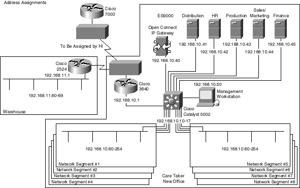
192.168.10.x for the main facility
-
192.168.11.x for the warehouse facility
-
192.168.20.x for the main-to-warehouse WAN
-
The last octet can be used to identify the network nodes on each network,
which will provide 254 nodes for each of the facilities (main and warehouse).
With this solution, the internal routers and PC/server nodes will support
a simple 255.255.255.0 subnet mask. This is an attractive solution because
it provides simplicity for an administrative staff that is not experienced
with routers. Use of a 255.255.255.0 mask on the WANs could be seen as
a waste, but there are so many addresses available that it is not important.
-
The nodes should then be grouped by class for ease of identification. For
example:
-
192.168.x.1 through 192.168.x.39 for the communications equipment
-
192.168.x.40 through 192.168.x.69 for the servers (file, print, mail, etc.)
and hosts
-
192.168.x.60 through 192.168.x.254 for the user nodes
-
The Windows NT DHCP should be installed on at least two of the Windows
NT servers (depending on their location). Use these servers to dynamically
assign IP addresses to the user computers.
2. Propose a plan for naming servers, routers,
and end nodes. Describe both the names themselves and the
method that will be used
to configure the names.
-
It would probably be best to name the servers with their department names
suffixed with the last octet of the node address, which will aid in troubleshooting.
The user nodes should have names that aid troubleshooting, such as the
letters "PC" followed by a "hyphen" and the user's first initial and last
name, such as PC-BSMITH.
-
Because CareTaker is a Windows NT only shop, the Windows NT DNS should
be installed as a local DNS, which will allow, at a minimum, addressing
the ES9000 with something like es9000.caretaker.com. You should use Cisco’s
DNS/DHCP Manager to synchronize DNS names with dynamically assigned IP
addresses from DHCP.
3. Update your topology diagram to reflect your
addressing scheme.
Click on the Back button in your browser to review Section 4 of Module
2. If you are finished with that section, click
here to go on to the PH Network Services Corporation case study.
Copyright Cisco Systems, Inc. -- Version 2.0 7/98


